
As we saw briefly in Database System Concepts ~ Introduction I, an E-R diagram can express the overall logical structure of a database graphically. E-R diagrams are simple and clear——qualities that may well account in large part for the widespread use of the E-R model.
1、Entity-Relationship Diagrams
The entity-relationship (E-R) data model uses a collection of basic objects, called entities, and relationships among these objects. An entity is a “thing” or “object” in the real world that is distinguishable from other objects.
1.1 Basic Structure
An E-R diagram consists of the following major components:
 Figure 1 E-R diagram corresponding to instructors and students.
- Rectangles divided into two parts represent entity sets. The first part, which in this series is shaded blue, contains the name of the entity set. The second part contains the names of all the attributes of the entity set.
- Diamonds represent relationship sets.
- Undivided rectangles represent the attributes of a relationship set. Attributes that are part of the primary key are underlined.
- Lines link entity sets to relationship sets.
- Dashed lines link attributes of a relationship set to the relationship set.
- Double lines indicate total participation of an entity in a relationship set.
- Double diamonds represent identifying relationship sets linked to weak entity sets.
Consider the E-R diagram in Figure 1, which consists of two entity sets, instructor and student related through a binary relationship set advisor. The attributes associated with instructor are ID, name, and salary. The attributes associated with student are ID, name, and tot_cred. In Figure 1, attributes of an entity set that are members of the primary key are underlined. If a relationship set has some attributes associated with it, then we enclose the attributes in a rectangle and link the rectangle with a dashed line to the diamond representing that relationship set. For example, in Figure 2, we have the date descriptive attribute attached to the relationship set advisor to specify the date on which an instructor became the advisor.
 Figure 2 E-R diagram with an attribute attached to a relationship set.
1.2 Mapping Cardinality
The relationship set advisor, between the instructor and student entity sets may be one-to-one, one-to-many, many-to-one, or many-to-many. To distinguish among these types, we draw either a directed line (->) or an undirected line (—) between the relationship set and the entity set in question, as follows:
- One-to-one: We draw a directed line from the relationship set advisor to both entity sets instructor and student (see Figure 3a). This indicates that an instructor may advise at most one student, and a student may have at most one advisor.
- One-to-many: We draw a directed line from the relationship set advisor to the entity set instructor and an undirected line to the entity set student (see Figure 3b). This indicates that an instructor may advise many students, but a student may have at most one advisor.
- Many-to-one: We draw an undirected line from the relationship set advisor to the entity set instructor and a directed line to the entity set student. This indicates that an instructor may advise at most one student, but a student may have many advisors.
- Many-to-many: We draw an undirected line from the relationship set advisor to both entity sets instructor and student (see Figure 3c). This indicates that an instructor may advise many students, and a student may have many advisors.
 Figure 3 Relationships. (a) One-to-one. (b) One-to-many. (c) Many-to-many.
E-R diagrams also provide a way to indicate more complex constraints on the number of times each entity participates in relationships in a relationship set. A line may have an associated minimum and maximum cardinality, shown in the form l . . h, where l is the minimum and h the maximum cardinality. A minimum value of 1 indicates total participation of the entity set in the relationship set; that is, each entity in the entity set occurs in at least one relationship in that relationship set. A maximum value of 1 indicates that the entity participates in at most one relationship, while a maximum value * indicates no limit.
For example, consider Figure 4. The line between advisor and student has a cordinality constraint of 1 .. 1, meaning the minimum and the maximum cardinality are both 1. That is, each student must have exactly one advisor. The limit 0 . . * on the line between advisor and instructor indicates that an instructor can have zero or more students. Thus, the relationship advisor is one-to-many from instructor to student, and further the participation of student in advisor is total, implying that a student must have an advisor.
 Figure 4 Cardinality limits on relationship sets.
It is easy to misinterpret the 0. .* on the left edge and think that the relationship advisor is many-to-one from instructor to student—this is exactly the reverse of the correct interpretation. If both edges have a maximum value of 1, the relationship is one-to-one. If we had specified a cardinality limit of 1..* on the left edge, we would be saying that each instructor must advise at least one student. The E-R diagram in Figure 4 could alternatively have been drawn with a double line from student to advisor, and an arrow on the line from advisor to instructor, in place of the cardinality constraints shown. This alternative diagram would enforce exactly the same constraints as the constraints shown in the figure.
1.3 Complex Attributes
Figure 5 shows how composite attributes can be represented in the E-R notation. Here, a composite attribute name, with component attributes first_name, middle_initial, and last_name replaces the simple attribute name of instructor. As another example, suppose we were to add an address to the instructor entity-set. The address can be defined as the composite attribute address with the attributes street, city, state, and zip_code. The attribute street is itself a composite attribute whose component attributes are street_number, street_name, and apartment_number. Figure 5 also illustrates a multivalued attribute phone_number, denoted by “{phone_number}”, and a derived attribute age, depicted by a “age ( )”.
 Figure 5 E-R diagram with composite, multivalued, and derived attributes.
1.4 Roles
We indicate roles in E-R diagrams by labeling the lines that connect diamonds to rectangles. Figure 6 shows the role indicators course_id and prereq_id between the course entity set and the prereq relationship set.
 Figure 6 E-R diagram with role indicators.
1.5 Nonbinary Relationship Sets
Nonbinary relationship sets can be specified easily in an E-R diagram. Figure 7 consists of the three entity sets instructor, student, and project, related through the relationship set proj_guide.
 Figure 7 E-R diagram with a ternary relationship.
We can specify some types of many-to-one relationships in the case of nonbinary relationship sets. Suppose a student can have at most one instructor as a guide on a project. This constraint can be specified by an arrow pointing to instructor on the edge from proj_guide. We permit at most one arrow out of a relationship set, since an E-R diagram with two or more arrows out of a nonbinary relationship set can be interpreted in two ways. Suppose there is a relationship set R between entity sets A1, A2, . . . , An, and the only arrows are on the edges to entity sets Ai+1, Ai+2, . . . , An, Then, the two possible interpretations are:
- A particular combination of entities from A1, A2, . . . , Ai can be associated with at most one combination of entities from Ai+1, Ai+2, . . . , An. Thus, the primary key for the relationship R can be constructed by the union of the primary keys of A1, A2, . . . , Ai.
- For each entity set Ak, i< k ≤ n, each combination of the entities from the other entity sets can be associated with at most one entity from Ak. Each set {A1, A2, . . . , Ak-1, Ak+1, . . . , An}, for i <k ≤ n, then forms a candidate key.
Each of these interpretations has been used in different books and systems. To avoid confusion, we permit only one arrow out of a relationship set, in which case the two interpretations are equivalent.
1.6 Weak Entity Sets
Consider a section entity, which is uniquely identified by a course identifier, semester, year, and section identifier. Clearly, section entities are related to course entities. Suppose we create a relationship set sec_course between entity sets section and course. Now observe that the information in sec_course is redundant, since section already has an attribute course_id, which identifies the course with which the section is related. One option to deal with this redundancy is to get rid of the relationship sec_course; however, by doing so the relationship between section and course becomes implicit in an attribute, which is not desirable.
An alternative way to deal with this redundancy is to not store the attribute course_id in the section entity and to only store the remaining attributes sec_id, year, and semester. However, the entity set section then does not have enough attributes to identify a particular section entity uniquely; although each section entity is distinct, sections for different courses may share the same sec_id, year, and semester. To deal with this problem, we treat the relationship sec_course as a special relationship that provides extra information, in this case the course_id, required to identify section entities uniquely.
The notion of weak entity set formalizes the above intuition. An entity set that does not have sufficient attributes to form a primary key is termed a weak entity set. An entity set that has a primary key is termed a strong entity set. For a weak entity set to be meaningful, it must be associated with another entity set, called the identifying or owner entity set. Every weak entity must be associated with an identifying entity; that is, the weak entity set is said to be existence dependent on the identifying entity set. The identifying entity set is said to own the weak entity set that it identifies. The relationship associating the weak entity set with the identifying entity set is called the identifying relationship.
The identifying relationship is many-to-one from the weak entity set to the identifying entity set, and the participation of the weak entity set in the relationship is total. The identifying relationship set should not have any descriptive attributes, since any such attributes can instead be associated with the weak entity set. In our example, the identifying entity set for section is course, and the relationship sec_course, which associates section entities with their corresponding course entities, is the identifying relationship.
Although a weak entity set does not have a primary key, we nevertheless need a means of distinguishing among all those entities in the weak entity set that depend on one particular strong entity. The discriminator of a weak entity set is a set of attributes that allows this distinction to be made. For example, the discriminator of the weak entity set section consists of the attributes sec_id, year, and semester, since, for each course, this set of attributes uniquely identifies one single section for that course. The discriminator of a weak entity set is also called the partial key of the entity set.
The primary key of a weak entity set is formed by the primary key of the identifying entity set, plus the weak entity set’s discriminator. In the case of the entity set section, its primary key is {course_id, sec_id, year, semester}, where course_id is the primary key of the identifying entity set, namely course, and {sec_id, year, semester} distinguishes section entities for the same course. Note that we could have chosen to make sec_id globally unique across all courses offered in the university, in which case the section entity set would have had a primary key. However, conceptually, a section is still dependent on a course for its existence, which is made explicit by making it a weak entity set. In E-R diagrams, a weak entity set is depicted via a rectangle, like a strong entity set, but there are two main differences:
- The discriminator of a weak entity is underlined with a dashed, rather than a solid, line.
- The relationship set connecting the weak entity set to the identifying strong entity set is depicted by a double diamond.
In Figure 8, the weak entity set section depends on the strong entity set course via the relationship set sec_course.
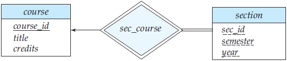 Figure 8 E-R diagram with a weak entity set.
The figure also illustrates the use of double lines to indicate total participation; the participation of the (weak) entity set section in the relationship sec_course is total, meaning that every section must be related via sec_course to some course. Finally, the arrow from sec_course to course indicates that each section is related to a single course.
A weak entity set can participate in relationships other than the identifying relationship. For instance, the section entity could participate in a relationship with the time_slot entity set, identifying the time when a particular class section meets. A weak entity set may participate as owner in an identifying relationship with another weak entity set. It is also possible to have a weak entity set with more than one identifying entity set. A particular weak entity would then be identified by a combination of entities, one from each identifying entity set. The primary key of the weak entity set would consist of the union of the primary keys of the identifying entity sets, plus the discriminator of the weak entity set.
In some cases, the database designer may choose to express a weak entity set as a multivalued composite attribute of the owner entity set. In our example, this alternative would require that the entity set course have a multivalued, composite attribute section. A weak entity set may be more appropriately modeled as an attribute if it participates in only the identifying relationship, and if it has few attributes. Conversely, a weak entity set representation more aptly models a situation where the set participates in relationships other than the identifying relationship, and where the weak entity set has several attributes. It is clear that section violates the requirement for being modeled as a multivalued composite attribute, and is modeled more aptly as a weak entity set.
1.7 E-R diagram for the University Enterprise
In Figure 9, we show an E-R diagram that corresponds to the university enterprise that we have been using thus far in the text. This E-R diagram is equivalent to the textual description of the university E-R model that we saw in earlier section, but with several additional constraints, and section now being a weak entity. In our university database, we have a constraint that each instructor must have exactly one associated department. As a result, there is a double line in Figure 9 between instructor and inst_dept, indicating total participation of instructor in inst_dept; that is, each instructor must be associated with a department. Further, there is an arrow from inst_dept to department, indicating that each instructor can have at most one associated department.
 Figure 9 E-R diagram for a university enterprise.
Similarly, entity sets course and student have double lines to relationship sets course_dept and stud_dept respectively, as also entity set section to relationship set sec_time_slot. The first two relationships, in turn, have an arrow pointing to the other relationship, department, while the third relationship has an arrow pointing to time_slot. Further, Figure 9 shows the relationship set takes has a descriptive attribute grade, and that each student has at most one advisor. The figure also shows that section is now a weak entity set, with attributes sec_id, semester, and year forming the discriminator; sec_course is the identifying relationship set relating weak entity set section to the strong entity set course.