
We can represent a database that conforms to an E-R database schema by a collection of relation schemas. For each entity set and for each relationship set in the database design, there is a unique relation schema to which we assign the name of the corresponding entity set or relationship set.1、Reduction to Relational Schemas
Both the E-R model and the relational database model are abstract, logical representations of real-world enterprises. Because the two models employ similar design principles, we can convert an E-R design into a relational design.
In this section, we describe how an E-R schema can be represented by relation schemas and how constraints arising from the E-R design can be mapped to constraints on relation schemas.
1.1 Representation of Strong Entity Sets with Simple Attributes
Let E be a strong entity set with only simple descriptive attributes a1, a2, …, an. We represent this entity by a schema called E with n distinct attributes. Each tuple in a relation on this schema corresponds to one entity of the entity set E. For schemas derived from strong entity sets, the primary key of the entity set serves as the primary key of the resulting schema. This follows directly from the fact that each tuple corresponds to a specific entity in the entity set.
As an illustration, consider the entity set student of the E-R diagram in Figure 9 in Database Design ~ Database Design and the E-R Model II. This entity set has three attributes: ID, name, tot_cred. We represent this entity set by a schema called student with three attributes:![]()
Note that since student ID is the primary key of the entity set, it is also the primary key of the relation schema. Continuing with our example, for the E-R diagram in Figure 9 in Database Design ~ Database Design and the E-R Model II, all the strong entity sets, except time_slot, have only simple attributes. The schemas derived from these strong entity sets are: As you can see, both the instructor and student schemas are different from the schemas we have used in the previous series (they do not contain the attribute dept_name). We shall revisit this issue shortly.
1.2 Representation of Strong Entity Sets with Complex Attributes
When a strong entity set has nonsimple attributes, things are a bit more complex. We handle composite attributes by creating a separate attribute for each of the component attributes; we do not create a separate attribute for the composite attribute itself. To illustrate, consider the version of the instructor entity set depicted in Figure 5 in Database Design ~ Database Design and the E-R Model II. For the composite attribute name, the schema generated for instructor contains the attributes first_name, middle_name, and last_name; There is no separate attribute or schema for name. Similarly, for the composite attribute address, the schema generated contains the attributes street, city, state, and zip_code. Since street is a composite attribute it is replaced by street_number, street_name, and apt_number.
Multivalued attributes are treated differently from other attributes. We have seen that attributes in an E-R diagram generally map directly into attributes for the appropriate relation schemas. Multivalued attributes, however, are an exception; new relation schemas are created for these attributes, as we shall see shortly. Derived attributes are not explicitly represented in the relational data model. However, they can be represented as “methods” in other data models such as the object-relational data model. which is described later.
The relational schema derived from the version of entity set instructor with complex attributes, without including the multivalued attribute, is thus: For a multivalued attribute M, we create a relation schema R with an attribute A that correspond to M and attributes corresponding to the primary key of the entity set or relationship set of which M is an attribute. As an illustration, consider the E-R diagram in Figure 5 in Database Design ~ Database Design and the E-R Model II that depicts the entity set instructor, which includes the multivalued attribute phone_number. The primary key of instructor is ID. For this multivalued attribute, we create a relation schema
![]() Each phone number of an instructor is represented as a unique tuple in the relation on this schema. Thus, if we had an instructor with ID 22222, and phone numbers 555-1234 and 555-4321, the relation instructor_phone would have two tuples (22222, 555-1234) and (22222, 555-4321).
Each phone number of an instructor is represented as a unique tuple in the relation on this schema. Thus, if we had an instructor with ID 22222, and phone numbers 555-1234 and 555-4321, the relation instructor_phone would have two tuples (22222, 555-1234) and (22222, 555-4321).
We create a primary key of the relation schema consisting of all attributes of the schema. In the above example, the primary key consists of both attributes of the relation instructor_phone. In addition, we create a foreign-key constraint on the relation schema created from the multivalued attribute, with the attribute generated from the primary key of the entity set referencing the relation generated from the entity set. In the above example, the foreign-key constraint on the instructor_phone relation would be that attribute ID references the instructor relation.
In the case that an entity set consists of only two attributes——a single primary——key attribute B and a single multivalued attribute M——the relation schema for the entity set would contain only one attribute, namely the primary-key attribute B. We can drop this relation, while retaining the relation schema with the attribute B and attribute A that corresponds to M.
To illustrate, consider the entity set time_slot depicted in Figure 9 in Database Design ~ Database Design and the E-R Model II. Here, time_slot_id is the primary key of the time_slot entity set and there is a single multivalued attribute that happens also to be composite. The entity set can be represented by just the following schema created from the multivalued composite attribute:![]() Although not represented as a constraint on the E-R diagram, we know that there cannot be two meetings of a class that start at the same time of the same day-of-the-week but end at different times; based on this constraint, end_time has been omitted from the primary key of the time_slot schema. The relation created from the entity set would have only a single attribute time_slot_id; the optimization of dropping this relation has the benefit of simplifying the resultant database schema, although it has a drawback related to foreign keys, which we briefly discuss in later section.
Although not represented as a constraint on the E-R diagram, we know that there cannot be two meetings of a class that start at the same time of the same day-of-the-week but end at different times; based on this constraint, end_time has been omitted from the primary key of the time_slot schema. The relation created from the entity set would have only a single attribute time_slot_id; the optimization of dropping this relation has the benefit of simplifying the resultant database schema, although it has a drawback related to foreign keys, which we briefly discuss in later section.
1.3 Representation of Weak Entity Sets
Let A be a weak entity set with attributes a1, a2, …, am. Let B be the strong entity set on which A depends. Let the primary key of B consist of attributes b1, b2, …, bn. We represent the entity set A by a relation schema called A with one attribute for each member of the set:![]() For schemas derived from a weak entity set, the combination of the primary key of the strong entity set and the discriminator of the weak entity set serves as the primary key of the schema. In addition to creating a primary key, we also create a foreign-key constraint on the relation A, specifying that the attributes b1, b2, …, bn references the primary key of the relation B. The foreign-key constraint ensures that for each tuple representing a weak entity, there is a corresponding tuple representing the corresponding strong entity.
For schemas derived from a weak entity set, the combination of the primary key of the strong entity set and the discriminator of the weak entity set serves as the primary key of the schema. In addition to creating a primary key, we also create a foreign-key constraint on the relation A, specifying that the attributes b1, b2, …, bn references the primary key of the relation B. The foreign-key constraint ensures that for each tuple representing a weak entity, there is a corresponding tuple representing the corresponding strong entity.
As an illustration, consider the weak entity set section in the E-R diagram of Figure 9 in Database Design ~ Database Design and the E-R Model II. This entity set has the attributes: sec_id, semester, and year. The primary key of the course entity set, on which section depends, is course_id. Thus, we represent section by a schema with the following attributes:![]()
The primary key consists of the primary key of the entity set course, along with the discriminator of section, which is sec_id, semester, and year. We also create a foreign-key constraint on the section schema, with the attribute course_id referencing the primary key of the course schema, and the integrity constraint “on delete cascade”. Because of the “on delete cascade” specification on the foreign key constraint, if a course entity is deleted, then so are all the associated section entities.
1.4 Representation of Relationship Sets
Let R be a relationship set, let a1, a2, …, am be the set of attributes formed by the union of the primary keys of each of the entity sets participating in R, and let the descriptive attributes (if any) of R be b1, b2, …, bn. We represent this relationship set by a relation schema called R with one attribute for each member of the set:![]() We described earlier, in section 3.3 in Database Design ~ Database Design and the E-R Model I, how to choose a primary key for a binary relationship set. As we saw in that section, taking all the primary-key attributes from all the related entity sets serves to identify a particular tuple, but for one-to-one, many-to-one, and one-to-many relationship sets, this turns out to be a larger set of attributes than we need in the primary key. The primary key is instead chosen as follows:
We described earlier, in section 3.3 in Database Design ~ Database Design and the E-R Model I, how to choose a primary key for a binary relationship set. As we saw in that section, taking all the primary-key attributes from all the related entity sets serves to identify a particular tuple, but for one-to-one, many-to-one, and one-to-many relationship sets, this turns out to be a larger set of attributes than we need in the primary key. The primary key is instead chosen as follows:
- For a binary many-to-many relationship, the union of primary-key attributes from the participating entity sets becomes the primary key.
- For a binary one-to-one relationship set, the primary key of either entity set can be chosen as the primary key. The choice can be made arbitrarily.
- For a binary many-to-one or one-to-many relationship set, the primary key of the entity set on the “many” side of the relationship set serves as the primary key.
- For an n-ary relationship set without any arrows on its edges, the union of the primary key-attributes from the participating entity sets becomes the primary key.
- For an n–ary relationship set with an arrow on one of its edges, the primary keys of the entity sets not on the “arrow” side of the relationship set serve as the primary key for the schema. Recall that we allowed only one arrow out of a relationship set.
We also create foreign-key constraints on the relation schema R as follows: For each entity set Ei related to relationship set R, we create a foreign-key constraint from relation schema R, with the attributes of R that were derived from primary-key attributes of Ei referencing the primary key of the relation schema representing Ei. As an illustration, consider the relationship set advisor in the E-R diagram of Figure 9 in Database Design ~ Database Design and the E-R Model II. This relationship set involves the following two entity sets:
- instructor with the primary key ID.
- student with the primary key ID.
Since the relationship set has no attributes, the advisor schema has two attributes, the primary keys of instructor and student. Since both attributes have the same name, we rename them i_ID and s_ID. Since the advisor relationship set is many-to-one from student to instructor the primary key for the advisor relation schema is s_ID. We also create two foreign-key constraints on the advisor relation, with attribute i_ID referencing the primary key of instructor and attribute s_ID referencing the primary key of student.
Continuing with our example, for the E-R diagram in Figure 9 in Database Design ~ Database Design and the E-R Model II, the schemas derived from a relationship set are depicted in Figure 10. Observe that for the case of the relationship set prereq, the role indicators associated with the relationship are used as attribute names, since both roles refer to the same relation course. Similar to the case of advisor, the primary key for each of the relations sec_course, sec_time_slot, sec_class, inst_dept, stud_dept and course_dept consists of the primary key of only one of the two related entity sets, since each of the corresponding relationship is many-to-one.
Foreign keys are not shown in Figure 10, but for each of the relations in the figure there are two foreign-key constraints, referencing the two relations created from the two related entity sets. Thus, for example, sec_course has foreign keys referencing section and classroom, teaches has foreign keys referencing instructor and section, and takes has foreign keys referencing student and section. Figure 1 Schemas derived from relationship sets in the E-R diagram in Figure 9 in Database Design ~ Database Design and the E-R Model II.
The optimization that allowed us to create only a single relation schema from the entity set time_slot, which had a multivalued attribute, prevents the creation of a foreign key from the relation schema sec_time_slot to the relation created from entity set time_slot, since we dropped the relation created from the entity set time_slot. We retained the relation created from the multivalued attribute, and named it time_slot, but this relation may potentially have no tuples corresponding to a time_slot_id, or may have multiple tuples corresponding to a time_slot_id; thus, time_slot_id in sec_time_slot cannot reference this relation.
The astute reader may wonder why we have not seen the schemas sec_course, sec_time_slot, sec_class, inst_dept, stud_dept, and course_dept in the previous series. The reason is that the algorithm we have presented thus far results in some schemas that can be either eliminated or combined with other schemas. We explore this issue next.
1.4.1 Redundancy of Schemas
A relationship set linking a weak entity set to the corresponding strong entity set is treated specially. As we noted in section 1.6 in Database Design ~ Database Design and the E-R Model II, these relationships are many-to-one and have no descriptive attributes. Furthermore, the primary key of a weak entity set includes the primary key of the strong entity set. In the E-R diagram of Figure 8 in Database Design ~ Database Design and the E-R Model II, the weak entity set section is dependent on the strong entity set course via the relationship set sec_course. The primary key of section is {course_id, sec_id, semester, year} and the primary key of course is course_id. Since sec_course has no descriptive attributes, the sec_course schema has attributes course_id, sec_id, semester, and year. The schema for the entity set section includes the attributes course_id, sec_id, semester, and year (among others). Every (course_id, sec_id, semester, year) combination in a sec_course relation would also be present in the relation on schema section, and vice versa. Thus, the sec_course schema is redundant.
In general, the schema for the relationship set linking a weak entity set to its corresponding strong entity set is redundant and does not need to be present in a relational database design based upon an E-R diagram.
1.4.2 Combination of Schemas
Consider a many-to-one relationship set AB from entity set A to entity set B. Using our relational-schema construction algorithm outlined previously, we get three schemas: A, B, and AB. Suppose further that the participation of A in the relationship is total; that is, every entity a in the entity set B must participate in the relationship AB. Then we can combine the schemas A and AB to form a single schema consisting of the union of attributes of both schemas. The primary key of the combined schema is the primary key of the entity set into whose schema the relationship set schema was merged.
To illustrate, let’s examine the various relations in the E-R diagram of Figure 9 in Database Design ~ Database Design and the E-R Model II that satisfy the above criteria:
- inst_dept. The schemas instructor and department correspond to the entity sets A and B, respectively. Thus, the schema inst_dept can be combined with the instructor schema. The resulting instructor schema consists of the attributes {ID, name, dept_name, salary}.
- stud_dept. The schemas student and department correspond to the entity sets A and B, respectively. Thus, the schema stud_dept can be combined with the student schema. The resulting student schema consists of the attributes {ID, name, dept_name, tot_cred}.
- course_dept. The schemas course and department correspond to the entity sets A and B, respectively. Thus, the schema course_dept can be combined with the course schema. The resulting course schema consists of the attributes {course_id, title, dept_name, credits}.
- sec_class. The schemas section and classroom correspond to the entity sets A and B, respectively. Thus, the schema sec_class can be combined with the section schema. The resulting section schema consists of the attributes {course_id, sec_id, semester, year, building, room_number}.
- sec_time_slot. The schemas section and time_slot correspond to the entity sets A and B respectively, Thus, the schema sec_time_slot can be combined with the section schema obtained in the previous step. The resulting section schema consists of the attributes {course_id, sec_id, semester, year, building, room_number, time_slot_id}.
In the case of one-to-one relationships, the relation schema for the relationship set can be combined with the schemas for either of the entity sets. We can combine schemas even if the participation is partial by using null values. In the above example, if inst_dept were partial, then we would store null values for the dept_name attribute for those instructors who have no associated department.
Finally, we consider the foreign-key constraints that would have appeared in the schema representing the relationship set. There would have been foreign-key constraints referencing each of the entity sets participating in the relationship set. We drop the constraint referencing the entity set into whose schema the relationship set schema is merged, and add the other foreign-key constraints to the combined schema. For example, inst_dept has a foreign key constraint of the attribute dept_name referencing the department relation. This foreign constraint is added to the instructor relation when the schema for inst_dept is merged into instructor.
2、Entity-Relationship Design Issues
The notions of an entity set and a relationship set are not precise, and it is possible to define a set of entities and the relationships among them in a number of different ways. In this section, we examine basic issues in the design of an E-R database schema.
2.1 Use of Entity Sets versus Attributes
Consider the entity set instructor with the additional attribute phone_number (Figure 2a.) It can easily be argued that a phone is an entity in its own right with attributes phone_number and location; the location may be the office or home where the phone is located, with mobile (cell) phones perhaps represented by the value “mobile.” If we take this point of view, we do not add the attribute phone_number to the instructor. Rather, we create:
- A phone entity set with attributes phone_number and location.
- A relationship set inst_phone, denoting the association between instructors and the phones that they have.
This alternative is shown in Figure 2b.
 Figure 2 Alternatives for adding phone to the instructor entity set.
What, then, is the main difference between these two definitions of an instructor? Treating a phone as an attribute phone_number implies that instructors have precisely one phone number each. Treating a phone as an entity phone permits instructors to have several phone numbers (including zero) associated with them. However, we could instead easily define phone_number as a multivalued attribute to allow multiple phones per instructor.
The main difference then is that treating a phone as an entity better models a situation where one may want to keep extra information about a phone, such as its location, or its type (mobile, IP phone, or plain old phone), or all who share the phone. Thus, treating phone as an entity is more general than treating it as an attribute and is appropriate when the generality may be useful. In contrast, it would not be appropriate to treat the attribute name (of an instructor) as an entity; it is difficult to argue that name is an entity in its own right (in contrast to the phone). Thus, it is appropriate to have name as an attribute of the instructor entity set.
Two natural questions thus arise: What constitutes an attribute, and what constitutes an entity set? Unfortunately, there are no simple answers. The distinctions mainly depend on the structure of the real-world enterprise being modeled, and on the semantics associated with the attribute in question.
A common mistake is to use the primary key of an entity set as an attribute of another entity set, instead of using a relationship. For example, it is incorrect to model the ID of a student as an attribute of an instructor even if each instructor advises only one student. The relationship advisor is the correct way to represent the connection between students and instructors, since it makes their connection explicit, rather than implicit via an attribute.
Another related mistake that people sometimes make is to designate the primary-key attributes of the related entity sets as attributes of the relationship set. For example, ID (the primary-key attributes of student) and ID (the primary key of instructor) should not appear as attributes of the relationship advisor. This should not be done since the primary-key attributes are already implicit in the relationship set.
2.2 Use of Entity Sets versus Relationship Sets
It is not always clear whether an object is best expressed by an entity set or a relationship set. In Figure 9 in Database Design ~ Database Design and the E-R Model II, we used the takes relationship set to model the situation where a student takes a (section of a) course. An alternative is to imagine that there is a course-registration record for each course that each student takes. Then, we have an entity set to represent the course-registration record. Let us call that entity set registration. Each registration entity is related to exactly one student and to exactly one section, so we have two relationship sets, one to relate course-registration records to students and one to relate course-registration records to section. In Figure 3, we show the entity sets section and student from Figure 9 in Database Design ~ Database Design and the E-R Model II with the takes relationship set replaced by one entity set and two relationship sets:
- registration, the entity set representing course-registration records.
- section_reg, the relationship set relating registration and course.
- student_reg, the relationship set relating registration and student.
Note that we use double links to indicate total participation by registration entities.
 Figure 3 Replacement of takes by registration and two relationship sets
Both the approach of Figure 9 in Database Design ~ Database Design and the E-R Model II and that of Figure 3 accurately represent the university’s information, but the use of takes is more compact and probably preferable. However, if the registrar’s office associates other information with a course-registration record, it might be best to make it an entity in its own right. One possible guideline in determining whether to use an entity set or a relationship set is to designate a relationship set to describe an action that occurs between entities. This approach can also be useful in deciding whether certain attributes may be more appropriately expressed as relationships.
2.3 Binary versus n-ary Relationship Sets
Relationships in databases are often binary. Some relationships that appear to be nonbinary could actually be better represented by several binary relationships. For instance, one could create a ternary relationship parent, relating a child to his/her mother and father. However, such a relationship could also be represented by two binary relationships, mother and father, relating a child to his/her mother and father separately. Using the two relationships mother and father provides us a record of a child’s mother, even if we are not aware of the father’s identity; a null value would be required if the ternary relationship parent is used. Using binary relationship sets is preferable in this case.
In fact, it is always possible to replace a nonbinary (n-ary, for n > 2) relationship set by a number of distinct binary relationship sets. For simplicity, consider the abstract ternary (n = 3) relationship set R, relating entity A, B, and C. We replace the relationship set R by an entity set E, and create three relationship sets as show in Figure 4:
- Ra, relating E and A.
- Rb, relating E and B.
- Rc, relating E and C.
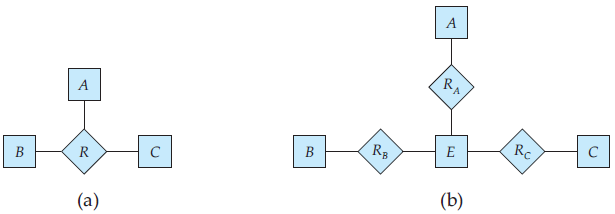 Figure 4 Ternary relationship versus three binary relationships.
If the relationship set R had any attributes, these are assigned to entity set E; further, a special identifying attribute is created for E (since it must be possible to distinguish different entities in an entity set on the basis of their attribute values). For each relationship (ai, bi, ci) in the relationship set R, we create a new entity ei in the entity set E. Then, in each of the three new relationship sets, we insert a relationship as follows:
- (ei, ai) in Ra.
- (ei, bi) in Rb.
- (ei, ci) in Rc.
We can generalize this process in a straightforward manner to n-ary relationship sets. Thus, conceptually, we can restrict the E-R model to include only binary relationship sets. However, this restriction is not always desirable.
- An identifying attribute may have to be created for the entity set created to represent the relationship set. This attribute, along with the extra relationship sets required, increases the complexity of the design and (as we shall see in section 1 in this article) overall storage requirements.
- An n-ary relationship set shows more clearly that several entities participate in a single relationship.
- There may not be a way to translate constraints on the ternary relationship into constraints on the binary relationships. For example, consider a constraint that says that R is many-to-one from A, B to C; that is, each pair of entities from A and B is associated with at most one C entity. This constraint cannot be expressed by using cardinality constraints on the relationship sets Ra, Rb, and Rc.
Consider the relationship set proj_guide in Section 2.2 in Database Design ~ Database Design and the E-R Model I, relating instructor, student, and project. We cannot directly split proj_guide into binary relationships between instructor and project and between instructor and student. If we did so, we would be able to record that instructor Katz works on projects A and B with students Shankar and Zhang; however, we would not be able to record that Katz works on project A with student Shankar and works on project B with student Zhang, but does not work on project A with Zhang or on project B with Shankar.
The relationship set proj_guide can be split into binary relationships by creating a new entity set as described above. However, doing so would not be very natural.
2.4 Placement of Relationship Attributes
The cardinality ratio of a relationship can affect the placement of relationship attributes. Thus, attributes of one-to-one or one-to-many relationship sets can be associated with one of the participating entity sets, rather than with the relationship set. For instance, let us specify that advisor is a one-to-many relationship set such that one instructor may advise several students, but each student can be advised by only a single instructor. In this case, the attribute date, which specifies when the instructor became the advisor of a student, could be associated with the student entity set, as Figure 5 depicts. (To keep the figure simple, only some of the attributes of the two entity sets are shown.) Since each student entity participates in a relationship with at most one instance of instructor, making this attribute designation has the same meaning as would placing date with the advisor relationship set. Attributes of a one-to-many relationship set can be repositioned to only the entity set on the “many” side of the relationship. For one-to-one relationship sets, on the other hand, the relationship attribute can be associated with either one of the participating entities.
The design decision of where to place descriptive attributes in such cases——as a relationship or entity attribute——should reflect the characteristics of the enterprise being modeled. The designer may choose to retain date as an attribute of advisor to express explicitly that the date refers to the advising relationship and not some other aspect of the student’s university status (for example, date of acceptance to the university).
The choice of attribute placement is more clear-cut for many-to-many relationship sets. Returning to our example, let us specify the perhaps more realistic case that advisor is a many-to-many relationship set expressing that an instructor may advise one or more students, and that a student may be advised by one or more instructors. If we are to express the date on which a specific instructor became the advisor of a specific student, date must be an attribute of the advisor relationship set, rather than either one of the participating entities. If date were an attribute of student, for instance, we could not determine which instructor became the advisor on that particular date. When an attribute is determined by the combination of participating entity sets, rather than by either entity separately, that attribute must be associated with the many-to-many relationship set. Figure 3 in Database Design ~ Database Design and the E-R Model I depicts the placement of date as a relationship attribute; again, to keep the figure simple, only some of the attributes of the two entity sets are shown.